
FURUNO RTR-078A 12kW Radar Transceiver
FURUNO Electric Co., Ltd.
New product
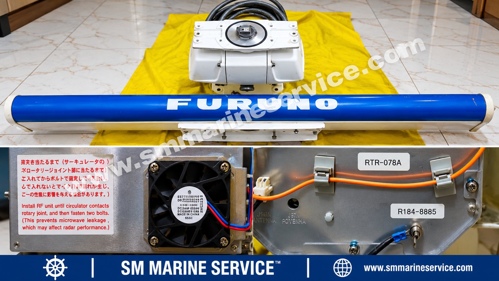
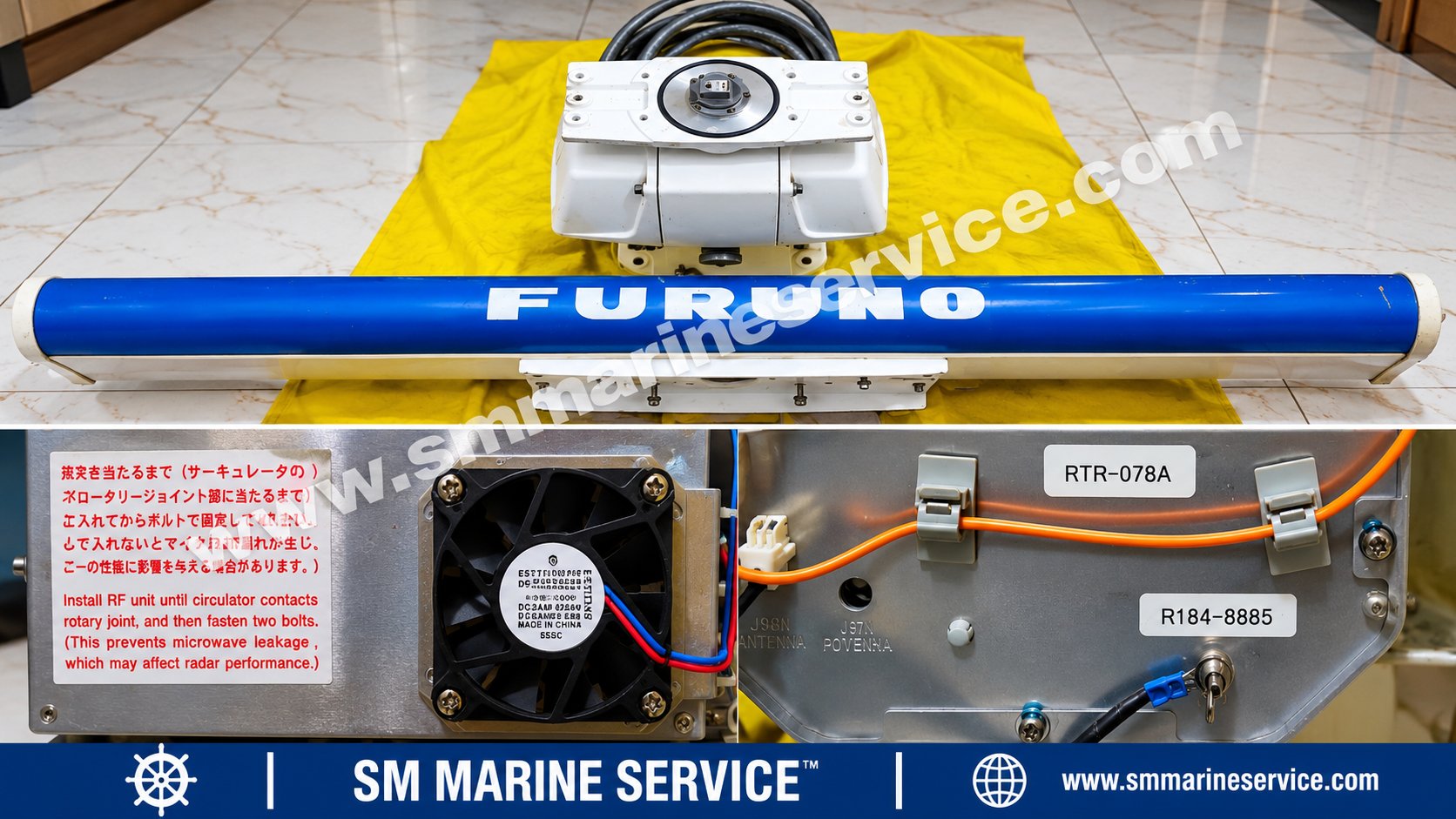
Original SM MARINE SERVICE™ photograph showing the FURUNO radar antenna assembly and RF transceiver-related hardware.
|
Specification |
Details |
|---|---|
|
Manufacturer |
FURUNO Electric Co., Ltd. |
|
Manufacturer Country |
Japan |
|
Product |
Radar Transceiver / RF Module |
|
Photographed Model |
RTR-078A |
|
Additional Visible Identifier |
R184-8885 |
|
Radar Band |
X-band |
|
Nominal Peak Output |
12 kW |
|
Nominal Transmitting Frequency |
Approximately 9410 MHz |
|
Applicable Radar Models |
FAR-2117, FAR-2117-BB, FAR-2817 family, subject to configuration |
|
Scanner Types |
RSB-096 / RSB-097, where applicable |
|
Radiator Models |
XN12AF / XN20AF / XN24AF |
|
Associated RF Boards |
RFC, MD, IF AMP, BP GEN, PWR |
|
Equipment Condition |
Not independently verified |
|
Availability |
Complete assembly and individual spare-part enquiries |
|
Worldwide Shipping |
Subject to stock and destination confirmation |
Identification note: The supplied photograph clearly shows RTR-078A and R184-8885. The second marking should be treated as an equipment identification label until its exact purpose is verified. It should not automatically be described as a manufacturer's serial number.
The FURUNO RTR-078A Radar Transceiver is an X-band radio-frequency module used inside compatible FURUNO marine radar scanner assemblies.
It is associated with the 12 kW FAR-2117 and FAR-2817 radar families, which are used aboard commercial vessels to detect surrounding targets and support navigation, collision avoidance and situational awareness.
The radar transceiver produces microwave transmission pulses and processes the returning radar echoes before transmitting the relevant received information to the radar processor.
The complete scanner assembly also includes the antenna radiator, rotation mechanism, rotary joint, monitoring electronics and other associated components.
For marine engineers, electronics officers, service technicians and international spare-parts buyers, correctly identifying the RTR-078A, along with its internal board numbers and related scanner type, is essential when purchasing replacement equipment.
SM MARINE SERVICE™ supports enquiries for complete RTR-078A radar transceiver assemblies, compatible radar scanner equipment and individual internal components, subject to availability and compatibility confirmation.
Website: www.smmarineservice.com
Original photograph showing the RTR-078A identification label, R184-8885 marking, cooling fan, RF installation warning and associated connections.
The photograph includes a warning about correct installation of the RF unit against the circulator and rotary joint.
This warning is important because an incorrectly seated RF module can create microwave leakage and compromise radar performance.
The RTR-078A is the radio-frequency transmission and reception section of a compatible FURUNO radar scanner.
During transmission, the transceiver generates high-power X-band radar pulses. The antenna radiator sends these pulses into the surrounding environment.
When radar echoes return from vessels, land, buoys and other reflective objects, the receiving circuitry processes these signals so that the radar display can present target information.
The transceiver is therefore a central part of radar performance, affecting transmission, echo reception and the quality of the signal delivered to the processor.
FURUNO documentation identifies the RTR-078 family with the 12 kW radar arrangement. The related RTR-079 family is associated with higher-power 25 kW configurations, and should not be treated as the same replacement unit.
12 kW nominal peak-power X-band transmission.
Associated with FURUNO FAR-2117 / FAR-2817 radar equipment.
Installed within a compatible radar antenna/scanner assembly.
RF controller and modulator electronics.
Magnetron-based microwave transmission.
Microwave receiving and intermediate-frequency amplification circuitry.
Power supply and monitoring electronics.
Compatibility with identified FURUNO scanner and radiator arrangements.
Built-in cooling fan in the photographed RF assembly.
Replaceable electronic boards subject to correct revision identification.
The exact hardware installed inside the photographed RTR-078A should be verified before supplying individual components.
|
Parameter |
Technical Information |
|---|---|
|
Manufacturer |
FURUNO Electric Co., Ltd. |
|
Transceiver Model |
RTR-078A |
|
Equipment Category |
Marine Radar RF Transceiver |
|
Frequency Band |
X-band |
|
Nominal Peak Output |
12 kW |
|
Nominal Operating Frequency |
Approximately 9410 MHz |
|
Associated Scanner |
RSB-096 / RSB-097 |
|
Antenna Rotation |
24 rpm / 42 rpm, according to scanner configuration |
|
Radiator Options |
XN12AF, XN20AF, XN24AF |
|
RFC Board Family |
03P9346 |
|
MD Board Family |
03P9244 |
|
IF Amplifier Board |
03P9335 |
|
Bearing Pulse Generator |
03P9347 |
|
RF Power Board |
03P9348 |
|
MIC Assembly |
RU-9601, configuration-dependent |
|
Magnetron |
MAF1565N in documented RTR-078A configurations |
|
Cooling Fan |
24 V DC, as supplied in product information |
|
Additional Visible Marking |
R184-8885 |
|
Equipment Serial Number |
Not independently verified |
|
Manufacturing Date |
Not verified |
|
Condition / Functional Testing |
Not confirmed |
FURUNO's available technical documentation identifies these RF assemblies and their component families, but board suffixes and installed magnetron versions can differ between production configurations. Confirm the exact fitted hardware rather than assuming compatibility from the base part number alone.
Individual PCB identifiers are particularly important for engineers repairing existing FURUNO radar transceivers.
The RFC board controls important radio-frequency transceiver functions and communicates with the radar processing equipment.
Its functions include coordinating transmission triggers, managing relevant RF control signals and monitoring selected operating parameters.
Applicable revisions may include 03P9346A or 03P9346B, depending on configuration.
The modulator board produces high-voltage pulses used to operate the magnetron.
For a 12 kW X-band RTR-078 configuration, manufacturer service information identifies 03P9244A as the relevant MD board version. Other suffixes may be assigned to different radar power levels.
The MD board is a safety-critical high-voltage assembly and must not be replaced with an arbitrary board sharing the same base identifier.
The intermediate-frequency amplifier processes the converted received signal.
A fault in this section can cause poor radar echo reception or abnormal received-signal performance.
The exact board identification and adjustment requirements must be checked before replacement.
The Bearing Pulse Generator board provides signals associated with antenna position and rotation.
These signals support the alignment of radar target information with antenna direction.
A faulty bearing or heading signal can affect correct radar presentation, although other components and connections may produce similar symptoms.
The RF power board provides electrical supplies required by the relevant transceiver circuitry.
Electrical measurements and replacements must be carried out according to FURUNO service procedures.
The microwave integrated circuit assembly forms part of the receiving signal path.
It participates in frequency conversion so that received X-band radar echoes can be processed by the intermediate-frequency circuitry.
FURUNO documentation identifies RU-9601 in relevant RTR-078A configurations. Confirm the installed assembly label before ordering.
The magnetron is the microwave-generating component in documented RTR-078A 12 kW configurations.
Magnetron performance can deteriorate with operating hours and condition, potentially affecting radar transmission and detection performance.
The actual fitted magnetron designation should be checked before ordering because radar production versions and earlier related models may use different components.
Other relevant components include the circulator, diode limiter, rotary joint, waveguide assembly, pulse transformer, cooling fan, antenna motor and scanner gearbox.
The photographed cooling fan and RF installation markings help identify the physical assembly but do not establish the electrical health of its internal components.
Close-up from the original photograph showing the RTR-078A and R184-8885 identification labels.
The visible module identification should be retained when requesting replacement parts.
The warning label instructs installers to seat the RF assembly correctly against the rotary joint before securing it. Improper assembly can result in microwave leakage and affect radar operation.
Only authorized, trained radar service personnel should carry out this work.
|
Radar / Equipment |
Relevant Configuration |
|---|---|
|
FAR-2117 |
12 kW X-band radar |
|
FAR-2117-BB |
Black-box variant of the 12 kW radar family |
|
FAR-2817 |
12 kW X-band radar |
|
RSB-096 |
Scanner arrangement rated for 24 rpm in documented configurations |
|
RSB-097 |
Scanner arrangement rated for 42 rpm in documented configurations |
|
XN12AF |
4 ft radiator |
|
XN20AF |
6.5 ft radiator |
|
XN24AF |
8 ft radiator |
|
RPU-013 |
Related radar processor unit |
|
RCU-014 / RCU-015 |
Related radar control units |
These associations appear in FURUNO's radar system configuration documentation. They do not guarantee that every board revision or scanner assembly can be substituted directly.
The short radiator visible in the supplied product photograph may resemble an XN12AF, but its exact designation must be confirmed by its label or physical dimensions.
The RTR-078A is used in compatible marine navigation radar systems.
Typical applications include merchant ships, bulk carriers, container vessels, tankers, offshore support vessels and other commercial ships equipped with the specified FURUNO radar family.
Radar supports the detection and tracking of surrounding targets, coastline observation, navigation in restricted visibility and collision-avoidance decision-making.
It must be operated as part of the vessel's complete navigation procedures, not as the sole source of navigational information.
|
Fault or Symptom |
Possible Cause |
Recommended Investigation |
|---|---|---|
|
No radar transmission |
Magnetron, modulator or RF control fault |
Examine approved radar diagnostics and transmission status |
|
Weak radar echoes |
Magnetron ageing, receiver problem or incorrect adjustment |
Assess transmitter and receiver performance |
|
No received echoes |
MIC, IF amplifier, antenna or signal-path issue |
Investigate the RF receiving chain |
|
Low magnetron current |
Magnetron, modulator or power-related fault |
Refer to manufacturer's service checks |
|
Bearing or heading indication error |
BP generator, antenna position signal or wiring fault |
Inspect approved scanner-position diagnostics |
|
Radar transmission trips |
Power or protection-related issue |
Record fault indications and investigate electrical conditions |
|
Cooling fan not operating |
Fan, cable or power fault |
Inspect cooling assembly after safe isolation |
|
Intermittent radar operation |
Loose connections, supply instability or internal fault |
Inspect the relevant equipment and connections |
|
Overheating |
Fan failure, blocked cooling or electronic fault |
Stop operation if required and arrange qualified inspection |
These are realistic fault categories for the associated radar system, not a verified diagnosis of the photographed unit.
A qualified radar technician should first record the radar model, transceiver type, scanner identification and observed fault conditions.
The investigation should then follow the approved service procedures for the complete radar system, including its power supply, processor, antenna controls and RF unit.
Do not assume that a faulty radar presentation necessarily means the RTR-078A has failed. Similar symptoms may originate in the antenna motor, processor unit, display, cable connections or other radar assemblies.
Safety warning: Marine radar transmitters contain high-voltage circuits and generate microwave radiation. Internal inspection, electrical measurements and RF testing must only be carried out by qualified personnel using approved isolation and service procedures. Never operate an incompletely assembled RF unit.
Regular maintenance of compatible FURUNO marine radar systems should include:
Checking scanner mounting and mechanical condition.
Inspecting accessible electrical and signal connections.
Monitoring antenna rotation and unusual mechanical noise.
Ensuring cooling paths are clear.
Recording operating faults and abnormal indications.
Inspecting the radar transceiver enclosure for corrosion and moisture ingress.
Reviewing magnetron operating condition through approved diagnostics.
Confirming correct radar performance after authorized repairs.
Mechanical or RF-unit maintenance should not be attempted while the scanner is energized or capable of rotating.
SM MARINE SERVICE™ supports worldwide enquiries for the FURUNO RTR-078A 12 kW X-band radar transceiver, complete radar scanner assemblies and compatible replacement components.
The supplied stock information identifies a complete RTR-078A antenna/transceiver assembly and states that internal RF boards and other components can also be supplied, subject to current stock confirmation.
Potential requirements include:
Complete RTR-078A radar transceiver.
Compatible RSB-096 / RSB-097 scanner assembly.
RFC board 03P9346.
MD board 03P9244.
IF amplifier board 03P9335.
BP GEN board 03P9347.
RF power board 03P9348.
RU-9601 MIC assembly.
Compatible magnetron and pulse transformer.
Cooling fan, cables, connectors and verified RF components.
Related FAR-2117 and FAR-2817 equipment.
New, used, refurbished, reconditioned or tested-working alternatives may be sourced depending on availability. The photographed unit's actual test status and condition have not been independently confirmed.
International buyers should provide the complete radar model, transceiver type, scanner model, radiator designation, internal PCB identification and hardware revision where available.
For individual PCB replacement, provide a clear photograph of the board label rather than relying only on the equipment model.
For a complete scanner enquiry, confirm the required antenna length, rotation speed, mounting arrangement and destination country.
Worldwide enquiries: www.smmarineservice.com
Vessels operating compatible FAR-2117 and FAR-2817 radar systems may need correctly matched replacement transceivers and internal boards to maintain the installed navigation arrangement.
Replacing an identified component can sometimes reduce the need for major changes to existing antennas, cabling, processors and operator controls.
However, the replacement must satisfy the radar system's configuration and applicable survey or approval requirements. The RTR-078A should not be automatically described as discontinued without confirming the manufacturer's current support status.
It is an X-band radar transceiver used within compatible FURUNO marine radar scanner assemblies.
It is associated with nominal 12 kW peak-power radar configurations.
Relevant equipment includes FAR-2117, FAR-2117-BB and FAR-2817 configurations, subject to exact compatibility verification.
It is an identification marking visible on the supplied module. Its exact classification as a serial, assembly or other identifier has not been confirmed.
The associated RFC board family is 03P9346. The correct suffix and revision must be checked.
The MD board family is 03P9244. The correct 12 kW board version must be verified before replacement.
MAF1565N is identified in available documentation for documented RTR-078A configurations. Check the actual fitted magnetron label.
No direct interchangeability should be assumed. RTR-079A is associated with 25 kW radar configurations, while RTR-078A belongs to the 12 kW family.
Potential causes include magnetron deterioration, receiver faults, antenna-system issues or incorrect radar settings.
Contact SM MARINE SERVICE™ for complete RF modules, scanner assemblies and compatible radar spare-parts enquiries.
SM MARINE SERVICE™ supports enquiries for different equipment conditions, subject to stock and suitability confirmation.
Worldwide shipping and international sourcing enquiries are accepted, subject to availability and destination arrangements.
The FURUNO RTR-078A 12 kW X-band Radar Transceiver is an RF module associated with FURUNO FAR-2117, FAR-2117-BB and FAR-2817 marine radar installations. The unit forms part of the radar scanner arrangement and contains radio-frequency transmission, reception, monitoring and control electronics. Related components include RFC board 03P9346, MD board 03P9244, IF amplifier 03P9335, BP GEN board 03P9347, RF power board 03P9348 and other configuration-dependent assemblies. SM MARINE SERVICE™ supports worldwide enquiries for complete radar transceivers, replacement boards, magnetrons and compatible marine radar spare parts. Buyers should confirm exact part numbers, revisions, condition and system compatibility before ordering.
Marine Automation & Navigation Equipment Supplier
Available Equipment Conditions:
New Equipment • Used Equipment • Refurbished Equipment • Reconditioned Equipment
Specific product condition and availability are subject to confirmation.
Stock Locations:
Bangladesh • China
Services:
Worldwide Shipping • Technical Support • Spare Parts Supply • Marine Equipment Sourcing
Contact Information
SM MARINE SERVICE™
Samir Market, DT Road, Pahartali, beside CDA Market, Chattogram, Bangladesh
Mobile / WhatsApp / Viber: +88 01818 929292
Email: info@smmarineservice.com
Website: www.smmarineservice.com
For quotations regarding FURUNO RTR-078A radar transceivers, compatible scanner assemblies, internal PCB boards, radar magnetrons and other marine navigation spare parts, contact SM MARINE SERVICE™ with your equipment identification photographs and shipping destination.
0
BDT 0
BDT 0
BDT 0
BDT 0
Marine Equipment Supplier