Boll & Kirch Electronic Control Box for Automatic Filter
Boll & Kirch
New product
Manufacturer: BOLL & KIRCH Filterbau GmbH
Brand: BOLLFILTER / BOLL & KIRCH
Manufacturer location: Kerpen, Germany
Country of origin of this individual unit: Not independently confirmed from the photograph
Exact controller model: Not visible in the supplied photograph
Part number: Not visible in the supplied photograph
Product type: Electronic control box for an automatic filter and backflushing system
Visible application label: “lubr. oil filter ME 2”
Visible electrical supply reference: “220 V~ 50 Hz”
Display: LCD-type display
Operator interface: Numeric keypad with 1–9, 0, J and N keys
Alarm indication: Red alarm indicator
Primary application: Main-engine lubricating-oil filtration
Other possible application: Fuel-oil filtration, subject to system configuration and compatibility
Product identification note: The photograph does not establish the exact model or part number of this control box. Filter types 6.60, 6.61, 6.62, 6.64 and 6.72 are referenced in the supplied application information as associated filter-system types; they are not confirmed model numbers for the pictured controller.
The BOLL & KIRCH electronic control box is a marine filtration control component used with compatible automatic filter systems. In a ship's engine room, an automatic filter helps remove contaminants from lubricating oil or another designated process liquid. The electronic controller manages and monitors the filter's operating sequence according to the installed system's design.
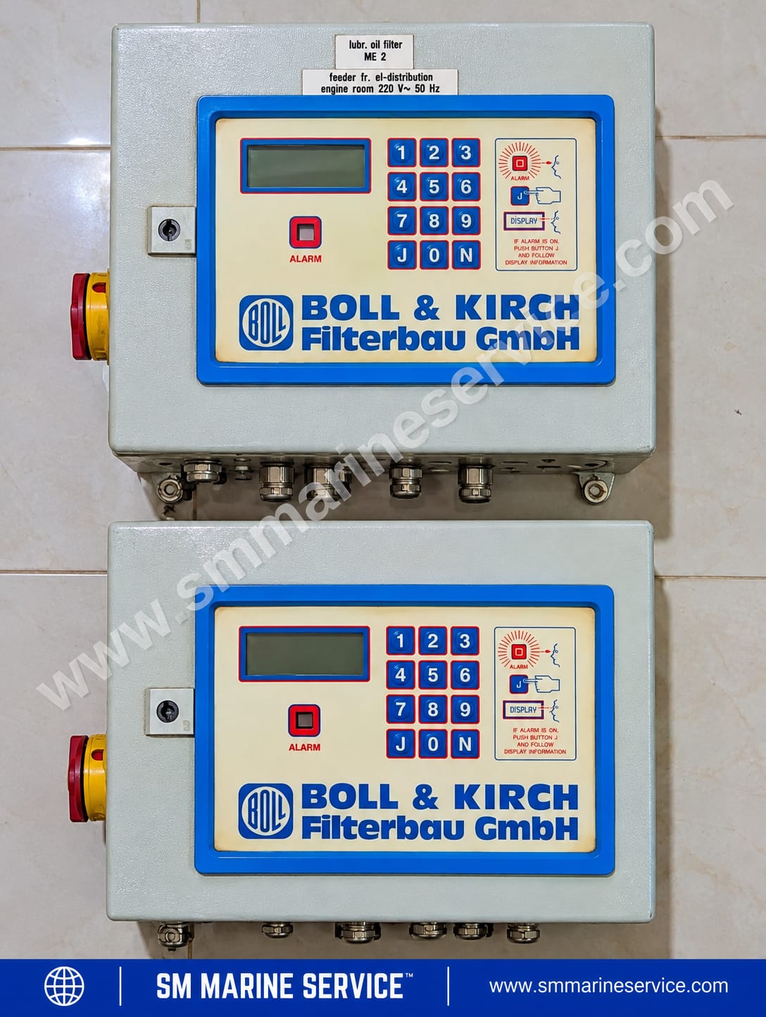
The supplied photograph shows an older-style control panel featuring an LCD-type display, numeric keypad, red alarm indicator, metal enclosure and external cable-entry fittings. The identification labels associate the pictured unit with a main-engine lubricating-oil filter and show a supply reference of 220 V AC, 50 Hz.
For marine engineers, electrical officers, technical superintendents, ship managers and purchasing departments, correct controller identification is essential when troubleshooting a filtration system, arranging repairs or sourcing a replacement unit.
SM MARINE SERVICE™ assists marine equipment buyers with identification and sourcing enquiries for automatic filter controllers, electronic spare parts and compatible replacement equipment, subject to availability and technical verification.
Main product image: Use the supplied photograph showing the complete control box, display, keypad, alarm indicator and visible application labels.
Suggested image alt text: BOLL & KIRCH electronic control box for marine automatic lubricating-oil filter with LCD display and numeric keypad.
Suggested image caption: Older-generation electronic control box associated with a main-engine lubricating-oil filter. Exact controller model and part number require confirmation.
For additional images, use genuine photographs of the installed filter system, the actual control-box nameplate, the internal electronic assembly and the relevant wiring diagram. Do not label a generic or unrelated component photograph as the exact pictured model.
An automatic filter electronic control box manages the electrical and control functions of a compatible automatic filtration system. Depending on the controller generation and installation, it may receive signals from differential-pressure switches or transmitters, initiate a backflushing sequence, monitor limit-switch feedback and activate alarm outputs.
During normal filtration, contaminants accumulate on the filter elements. As the filter becomes loaded, the differential pressure across the filter may rise. When the configured starting condition is reached, the automatic filter system can begin a cleaning sequence.
The controller may perform functions such as:
Monitoring operating conditions and control inputs.
Initiating backflushing based on configured differential-pressure or time conditions.
Operating the relevant flushing mechanism or valves.
Monitoring position or sequence feedback from limit switches.
Activating alarm indications or configured external alarm outputs.
Displaying operating information for the operator.
Recording flushing cycles or alarm information where supported by the specific controller.
The exact functions depend on the controller model, configuration, electrical design and connected filter system. The exterior photograph alone cannot verify every function for this particular unit.
Lubricating oil passes through the filter elements while contaminants are retained by the filtration system. The oil continues through the designed flow path while the filter performs its normal function.
Differential pressure (DP) is the difference between pressure measured on the dirty side and the clean side of a filter. As contaminants accumulate, the differential pressure may increase.
The supplied system description identifies two example thresholds:
DP reached — approximately 75%: A configured threshold associated with initiating backflushing.
DP too high — approximately 100%: A higher threshold associated with an alarm.
These percentages are supplied application information and should not be treated as universal settings for every filter or controller. Actual switching values must be confirmed from the applicable system documentation.
When the configured start condition is met, the controller initiates the cleaning sequence. Depending on the filter design, this may involve a flushing valve, a drive mechanism or other mechanical components.
The objective is to remove accumulated contamination from the filter elements while maintaining filtration according to the system's design.
The controller may monitor limit switches or other feedback signals to determine whether the sequence is progressing as expected. Missing feedback, a failed actuator or an abnormal input can prevent the sequence from completing and may cause an alarm.
When an alarm is indicated, the operator should check the display, identify the underlying condition and follow the approved operating procedure. Acknowledging an alarm does not necessarily correct the cause.
Suggested additional image: A clearly labelled diagram showing an automatic filter, differential-pressure measurement, electronic controller and backflushing mechanism. Use a diagram that matches the installed system wherever possible.
The control box includes a rectangular LCD-type display for operator information. The exact menu structure, displayed parameters and diagnostic functions have not been confirmed for the pictured controller.
The faceplate includes numeric keys 1–9, 0 and the letters J and N. The instruction label indicates that J is used in an alarm-related display procedure. Consult the correct controller manual to confirm the precise function of each key.
A red indicator labelled “ALARM” provides a visible warning when an alarm condition is active. The operator should investigate the actual fault instead of assuming that every alarm indicates the same problem.
The controller is installed in a metal enclosure with visible cable-entry fittings. These provide routes for external electrical connections. Terminal assignments and wiring details cannot be identified from the exterior photograph.
The visible label associates the pictured unit with a main-engine lubricating-oil filter. The label also provides a 220 V AC, 50 Hz supply reference. Before installation or energization, confirm the actual electrical requirements against the equipment identification and approved vessel documentation.
Depending on the system configuration, the controller may coordinate backflushing, monitor input signals and activate alarm outputs. The actual available functions must be verified against the installed controller and filter model.
The following information separates details visible in the photograph from details that require confirmation.
| Parameter | Details |
|---|---|
| Manufacturer | BOLL & KIRCH Filterbau GmbH |
| Manufacturer location | Kerpen, Germany |
| Country of origin of pictured unit | Not independently confirmed |
| Product category | Electronic automatic-filter control box |
| Exact controller model | Not visible in the photograph |
| Part number | Not visible in the photograph |
| Visible application | Main-engine lubricating-oil filter |
| Supply reference on label | 220 V AC, 50 Hz |
| Operator display | LCD-type display |
| Keypad | Numeric keys 1–9, 0, J and N |
| Alarm indication | Red alarm indicator |
| Enclosure | Metal enclosure |
| External connections | Cable-entry fittings visible |
| Input signals | System-dependent; verify from the wiring diagram |
| Output signals | System-dependent; verify from the wiring diagram |
| Associated filter types | 6.60, 6.61, 6.62, 6.64 and 6.72 are listed in the supplied application information; compatibility requires confirmation |
| Potential replacement options | Type 2200, Type 2300 and Type 2300Plus are mentioned in the supplied information; suitability is not confirmed |
| Condition of pictured unit | Cannot be determined from the photograph alone |
Important: This table is not a substitute for a nameplate, wiring diagram or approved technical specification. The visible supply reference is an identification clue, not sufficient proof that the controller is compatible with every vessel's electrical system.
The following items may form part of an automatic filter installation. Their presence and exact specifications must be confirmed for the actual system.
The main enclosure contains the operator interface and internal control electronics. The internal board arrangement and component numbers of the pictured unit are not visible.
The display presents operating information, while the keypad enables operator interaction. The exact menu functions and operating sequence depend on the controller generation.
Differential-pressure devices monitor the pressure difference across the filter. Depending on the installation, the system may use discrete pressure switches, an analogue transmitter or a combination of signals.
The supplied product information mentions a 4–20 mA differential-pressure transmitter as a possible input. This does not confirm that the pictured controller accepts that signal directly; the input design must be verified.
Limit switches can provide position or sequence feedback from the mechanical assembly. Incorrect feedback may prevent a flushing sequence from completing or may trigger an alarm.
These components perform the mechanical cleaning sequence. The arrangement depends on the filter design and must be checked against the relevant system documentation.
An electronic controller may contain a printed circuit board, power-supply circuitry, relays, input circuits and terminal connections. The actual component types, board numbers and replaceable parts in the pictured unit have not been identified.
A configured relay output may communicate an alarm to the vessel's monitoring system. Confirm the contact arrangement, terminal numbers and electrical ratings from the correct wiring diagram.
Suggested additional image: A photograph of the actual internal controller PCB or a wiring diagram matched to the identified control box. Do not use an unrelated electronic board as a representation of the pictured unit's internal components.
The visible application label identifies the pictured panel with a main-engine lubricating-oil filter. Effective oil filtration helps protect engine bearings and other lubricated components from harmful contamination. The controller supports the operation and monitoring of the compatible automatic filter system.
Compatible automatic filtration systems may also be used in fuel-oil applications. A controller associated with a lubricating-oil filter should not automatically be considered suitable for fuel-oil service. The filter model, configuration, control sequence and electrical arrangement must match.
Depending on the installed filtration equipment, automatic filter control systems may be used on cargo vessels, tankers, bulk carriers, container vessels and other commercial ships.
Marine electrical officers, engine-room personnel and service engineers may need to identify the controller during routine inspections, troubleshooting, filter maintenance and spare-parts procurement.
The following are practical fault-finding categories for automatic filter control systems. They are not confirmed fault reports for the specific pictured controller. Always follow the applicable operating manual and vessel safety procedures.
Possible causes:
Loss of incoming electrical supply.
Tripped protective device or open isolator.
Loose or damaged wiring.
Internal power-supply failure.
Incorrect supply voltage or frequency.
Recommended checks:
Confirm the vessel supply and equipment electrical requirements.
Check relevant protective devices and the supply circuit.
Inspect accessible external wiring for damage after appropriate isolation.
Ask a qualified marine electrical engineer to test the internal supply circuit if the external supply is correct.
Do not work on an energized enclosure unless the applicable procedure and personnel qualifications specifically permit it.
Possible causes:
No incoming power.
Internal control-voltage failure.
Display or connection fault.
Internal electronic failure.
Recommended checks:
Establish whether the correct supply is present.
Check whether any other indicator is illuminated.
Inspect internal connections only after proper electrical isolation.
Consult the correct controller documentation before replacing the display or PCB.
Possible causes:
Excessive contamination in the filter elements.
A genuine increase in differential pressure.
A faulty pressure switch or transmitter.
Blocked or damaged pressure-sensing lines.
Incorrect configuration or wiring.
Recommended checks:
Verify the actual differential pressure using an approved method.
Inspect the pressure-sensing arrangement.
Check the filter condition and follow the approved cleaning procedure.
Compare the measured condition with the specified alarm threshold.
Do not change pressure thresholds merely to silence an alarm. A genuine high differential pressure may indicate a filtration problem that needs attention.
Possible causes:
The configured start threshold has not been reached.
A pressure-switch or transmitter signal is missing or incorrect.
A controller input or configuration fault.
A flushing valve or drive is not ready.
A required interlock or feedback signal is absent.
Recommended checks:
Check the actual differential pressure and configured time-based settings, where applicable.
Confirm input signals using the correct wiring diagram.
Inspect the associated mechanical equipment and its permitted operating status.
Do not bypass interlocks or force outputs without an approved test procedure.
Possible causes:
A mechanical actuator or valve fails to move correctly.
A limit switch does not provide the expected feedback.
A cable, connector or input circuit is faulty.
Sequence timing or configuration does not match the installed filter.
Recommended checks:
Observe the sequence from a safe position.
Verify expected mechanical movement and feedback signals.
Inspect the relevant switch, actuator and wiring according to the approved isolation procedure.
Use the system-specific manual to confirm the expected sequence.
If the installed filter uses a motor-driven mechanism, a motor-related alarm may result from a supply problem, protective-device operation, wiring damage, motor failure or a mechanical obstruction.
Confirm the actual motor arrangement and alarm circuit for the installed filter. Do not assume that every automatic filter uses the same motor or drive configuration.
A control-voltage alarm may indicate that the monitored supply is outside its specified operating condition or is unavailable. Verify the supply, protective devices, wiring and internal power-supply circuit using the relevant electrical documentation.
A limit-switch alarm may indicate that the controller has not received the expected position or sequence feedback. Possible causes include mechanical movement problems, switch adjustment, switch failure, wiring damage or an input-circuit fault.
Intermittent faults may result from loose connections, vibration-related damage, moisture ingress, ageing components or unstable power. Inspect the enclosure, cable entries, terminal connections and relevant circuits according to the correct isolation and inspection procedure.
Acknowledging an alarm is not the same as repairing the cause. If the monitored condition remains abnormal, the alarm may return. Confirm and correct the underlying fault before following the controller's documented reset procedure.
The supplied application information identifies the following alarm categories:
Differential-pressure alarm.
Motor fault alarm.
Control-voltage monitoring alarm.
Limit-switch alarm.
General or external alarm output, depending on the configuration.
These are functional descriptions, not verified display messages or alarm codes for the pictured control box. No specific alphanumeric fault code can be confirmed from the photograph.
Before interpreting a displayed message, changing parameters or resetting an alarm, identify the controller model and consult the applicable operating instructions and filter documentation.
Check the enclosure for corrosion, impact damage and loose mounting.
Inspect cable entries and glands for damage or signs of moisture.
Check the display and alarm indicator during normal operating checks.
Investigate and record alarm events according to vessel procedures.
Follow the manufacturer's isolation and electrical-safety instructions before opening the enclosure.
Have qualified personnel inspect terminals, protective devices and relevant connections.
Verify the incoming supply against the equipment identification and approved documentation.
Do not replace electronic parts based solely on visual similarity.
Compare the measured or indicated differential pressure with the filter's approved operating limits.
Inspect pressure-sensing lines, switches and transmitters according to the maintenance instructions.
Investigate unusually frequent backflushing instead of assuming that the controller is defective.
Check the associated valve, actuator or motor according to the filter maintenance procedure.
Confirm that limit-switch feedback matches the mechanical sequence.
Use only the prescribed procedure for manual operation and functional testing.
Keep the controller model, serial number, program identification, filter type and wiring diagram with maintenance records.
Record original terminal connections before authorized maintenance work.
Confirm replacement compatibility before ordering a controller, PCB or other electronic component.
SM MARINE SERVICE™ supports marine equipment sourcing enquiries for older automatic filter controllers and related electronic spare parts, subject to availability and technical identification.
Potential sourcing enquiries may include:
Complete electronic control box.
LCD display assembly.
Keypad or operator interface.
Main controller PCB.
Power-supply components.
Relay and input/output components.
Terminal blocks and connectors.
Wiring and cable assemblies.
Compatible differential-pressure switches or transmitters.
Limit switches and related electrical components.
Filter-related actuators, motors or flushing components, where applicable.
These are possible sourcing categories, not confirmation that every component is independently replaceable or available for the pictured unit. Component-level repairs require actual board and component identification.
The supplied product information identifies Type 2200, Type 2300 and Type 2300Plus as potential newer-generation options. Their suitability for the pictured control box has not been confirmed.
A newer controller is not automatically a direct or plug-and-play replacement. Before selecting a replacement, verify:
The exact model and program identification of the existing controller.
The installed filter type and its configuration.
The incoming supply and control-voltage requirements.
Input signal types and terminal assignments.
Output and relay requirements.
Limit-switch, valve and motor arrangements.
Any required manufacturer-approved modification or commissioning procedure.
Where the original model is known, the relevant modification documentation may help establish whether a conversion is supported. Do not apply a modification procedure until the original controller and its applicability have been confirmed.
Depending on stock and sourcing results, SM MARINE SERVICE™ can assist with enquiries for:
New equipment.
Used equipment.
Refurbished equipment.
Reconditioned equipment.
Tested working equipment.
Actual availability, condition, warranty and compatibility must be confirmed for each quotation. Buyers should provide clear photographs of the complete control box, its identification labels and the associated filter model. Internal photographs should only be taken after appropriate isolation by qualified personnel.
Older electronic controllers may remain in service because they are integrated into a functioning filtration installation and configured for the vessel's existing equipment. Replacing a controller can require wiring changes, configuration work, functional testing and technical approval rather than a simple exchange of the enclosure.
For ship operators, the objective is to maintain safe and reliable filtration while preserving compatibility with the installed system. An appropriately identified replacement or professionally assessed repair may help reduce downtime and avoid unnecessary modifications.
The decision to repair or replace should consider the controller's condition, spare-parts availability, system criticality, documentation and the applicable technical recommendations.
It is an electronic controller used with a compatible automatic filtration system to manage and monitor filtration functions. Depending on the configuration, it may coordinate backflushing and monitor pressure-related inputs, limit switches and alarm outputs.
The manufacturer is BOLL & KIRCH Filterbau GmbH, located in Kerpen, Germany.
The exact model and part number are not visible in the supplied photograph. The labels identify a main-engine lubricating-oil filter application and a 220 V AC, 50 Hz supply reference, but further identification is required.
The supplied application information lists filter types 6.60, 6.61, 6.62, 6.64 and 6.72. Exact compatibility with the pictured controller must be confirmed from the applicable documentation.
It indicates that the differential-pressure condition monitored by the installed system has reached its configured alarm condition. Possible causes include filter contamination, a genuine pressure rise, faulty sensing equipment or a signal or wiring problem. The actual cause must be investigated.
Acknowledgement may confirm or silence an alarm indication, but it does not remove the underlying fault. If the abnormal condition persists, the alarm may return.
A replacement may be possible, but compatibility cannot be determined from the exterior photograph alone. The original controller type, filter model, supply, inputs, outputs and wiring must be checked before selecting a replacement.
Availability depends on the controller's actual model and internal component identification. Provide clear photographs and any available model, serial or circuit-board numbers to support identification.
SM MARINE SERVICE™ can assist with enquiries for used, refurbished, reconditioned or tested equipment, depending on availability. The exact model and application should be provided to reduce the risk of an incompatible supply.
Use the technical resources section below to locate documentation for the identified controller and filter type. A manual for a different controller generation should not be assumed to cover the pictured unit.
SM MARINE SERVICE™ accepts marine equipment and spare-parts enquiries from international buyers and can assist with worldwide shipping arrangements, subject to availability, shipping requirements and quotation confirmation.
BOLL & KIRCH Electronic Control Box for Marine Automatic Filter — an older-generation electronic control panel associated with a main-engine lubricating-oil filtration application. The pictured unit features an LCD-type display, numeric keypad, red alarm indicator and a label referring to a 220 V AC, 50 Hz supply. The exact controller model and part number are not visible in the photograph. Contact SM MARINE SERVICE™ for identification assistance, replacement enquiries, spare parts and sourcing of new, used, refurbished or reconditioned equipment, subject to availability.
The exact model of the pictured controller has not been established. Before using a manual for maintenance, wiring, replacement or commissioning, confirm that it matches the actual controller and filter installation.
Document: BOLLFILTER Type 2200 operating and installation instructions.
Use the manufacturer's Type 2200 manual only if the installed controller is confirmed as Type 2200 or the document is otherwise verified as applicable.
Document: BOLLFILTER Type 2300 operating instructions.
Confirm the controller model before applying its operating or configuration procedures.
Document: BOLLFILTER Type 2300Plus operating instructions.
Confirm the model and system compatibility before using instructions for this controller generation.
Use the wiring diagram that matches the actual filter type, controller model and installation configuration. Do not infer terminal numbers, signal types or relay ratings from the exterior photograph.
The model-specific documents listed above should be obtained from the equipment's verified documentation source. No direct manual URL is provided here because the exact controller model shown in the photograph has not been confirmed and the documents must be checked for authenticity and applicability before publication.
SM MARINE SERVICE™
Marine Automation & Navigation Equipment Supplier
Available Condition:
• New Equipment • Used Equipment • Refurbished Equipment • Reconditioned Equipment
Stock Location:
• Bangladesh • China
Services:
• Worldwide Shipping • Technical Support • Spare Parts Supply • Marine Equipment Sourcing
Contact Information
SM MARINE SERVICE™ Samir Market, DT Road, Pahartali, beside CDA Market, Chattogram, Bangladesh
Mobile / WhatsApp / Viber: +88 01818 929292
Email: info@smmarineservice.com
Website: www.smmarineservice.com
0

BDT 0

BDT 0

BDT 0

BDT 0
Marine Equipment Supplier